The parallel port is disappearing slowly. First a bit about PC’s
There are essentially two types of Windows Motherboards 32 bit and 64 bit. 32 bit systems are older, and supported WinXP (and older OS) and Windows 7 32 bit, they typically came with a parallel port from the factory. MACH3 WILL ONLY WORK ON PARALLEL PORT WITH 32 BIT SYSTEMS. If you have a Windows XP computer it is most likely 32 bit and standard parallel port operation will work with Mach3, if you have a Windows 7 computer it is either 32 or 64 bit. The way to find out: Click on the globe or “start” in the lower left of the desktop screen the command line will pop up, type in “dxdiag”, it will ask if you’d like to check the drivers digital signature just answer “yes”. A field will open that tells you everything about the PC, next to the “operating system” it will note 32 or 64 bit. It’s that easy. If it’s 32 bit, you can use standard parallel port communication and use the cable we include with the machine.
If it is determined that the computer is Win7 64 bit or Win10 64 bit, then an adapter is needed to communicate with the Romaxx. It’s called a UC100, it is available on our router accessories page or on Amazon. Purchase only the “UC100” made by “CNCDrive”, there are several fake units available around the web that look just like it but will not work, and no other same type plug and play inline USB to Parallel converters (computer store accessories) will work that we know of. There are some other more sophisticated printed circuit board types that will work , USB and Ethernet, but they are more difficult to setup and offer no real advantage (that we know of) and are more expensive. (ESS, UC400 etc)
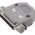
The UC100 will need a driver installed which is available from cncdrive.com :
http://www.cncdrive.com/UC100.html
Also available here:
UC100 Manual
UC100 Installer
Tip: For Installing this UC100 driver/plug-in for Mach3, make sure to reboot the PC after installation, on some PC’s this is required to finish the driver installation.
It means a lot! The machine arrives fully assembled tested and ready to use, it’s not a box of parts that have to be assembled. Our machine is ready to uncrate, connect it to a PC’s printer or USB and Ethernet port with optional adapter and operate it as a 3 axis CNC platform. We don’t include a spindle with machine only, as many folks have a preference to the type of spindle they want to use for the specific type of work they are doing. Our combination packages do include a spindle. Some customers use the Romaxx for rapid prototyping with a syringe type injection head while others maybe using it for a 3D digitizing system with a probe. The Dewalt 611 router that we offer as an option is a good candidate for general woodworking and plastics machining, It’s 1-1/4 horsepower and accepts standard 1/4″ router bits.
There are countless methods of doing this. What we found to be the easiest for most work is just two-sided carpet tape. Of course, a better means is to mechanically hold the work, with a vise or clamps, etc. The best mechanical means known to us for this type of machining operation is the Incra style hold down clamping system sold at Amazon and woodworking stores. A vacuum table could be used as well, made with some MDF and a shop vac as a vacuum source. When using an MDF table you can screw right into it, to hold fixtures, vises, vacuum- tables, etc. Another good way to hold wood pieces down to the MDF spoilboard is a glue called 2P-10 which is essentially SuperGlue for wood. Just position the piece and apply a drop every few inches around where the part meets the MDF, then it can be separated with a wood chisel, works great for making 3D casting patterns etc.
The cast aluminum table options with tapped and reamed holes makes this much easier
MPG stands for Manual Pulse Generator and is basically an electronic hand-wheel. It’s the silver dial on the front of the machine in the picture to the upper right. By selecting it’s function in Mach3, when the user rotates the MPG it moves the selected axis. It has 100 detents per revolution and each detent or hash line equals approximately .001″ of linear movement. It is an asset when referencing the cutter to the work and a neat way to jog the spindle around.
Other than keeping it clean of sawdust and not letting it build up on the rails, etc. The machine requires no scheduled maintenance. All the bearings are sealed and lubricated. The few bushings it uses are oil-lite bronze and require no lubrication. We designed it with as few moving parts as possible and every component was selected with long service life and low maintenance operation in mind. The timing belts are very high quality steel lined poly. We have one older CNC machine in our shop with just neoprene glass lined belts that are 30 years old, still working fine and was the inspiration for this machine design. All the timing pulleys are high quality machined aluminum, again, requiring no maintenance.
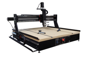
Yes! We opted for MDF as a good basic table that is flat and very inexpensive to replace. It just bolts to the upper surface of the machine base. As is the case with many routing operations, the cutter may extend through the workpiece into the table’s surface. It is because of this that most users prefer to attach an inexpensive table surface as a spoil board which can be inexpensively changed out occasionally. Also we have as an option the Cast aluminum tooling table with predrilled and tapped holes which makes securing fixtures and work very easy.
Absolutely we can and always have ever since 2006 since we started building CNC machines, we are always just an email or phone call away. Our e-mail is monitored closely and you will receive an answer to your question in prompt order. We don’t offer training, but we will assist you in making your CNC machining experience a success. There is a wealth of information on the web such as, https://www.machsupport.com/forum/index.php , this is the website for Mach3. There are instructional videos available for download as well as an reference manual.
This is a very common question and there are many available software products to complete this process. It is essentially three basic steps, just remember, CAD-> CAM-> CNC. The design phase, putting your idea on the screen, is done in a CAD program, and this can be any CAD software that will output a file format that a CAM type software can interpret. Common types are DXF and IGS formats. Once a drawing is completed and exported in DXF perhaps, it is opened up in a CAM type program like “Sheetcam” or “Meshcam”. This is where the actual G-code generation takes place. G-code is the common term for the programming language that the CNC controller reads and converts into motion. Once the G-code is generated and saved, it is then loaded in Mach3 and ran. Folks that are proficient with the above process can do simple parts in less than a minute and have the machine ready to go. There are many different software packages available. Some like “Bobcadcam”, are 3D CAD and CAM integrated together in one suite. Mach3 also includes L-CAM for free to use and supports 2.5 D tool path and code generation and supports DXF import. Some people even code parts by hand. Knowing the commands and not minding the math involved, it is a popular means of producing G-code. Newfangled Solutions’ offer a suite of “wizards” for Mach 3 that tackle common tasks such as hole patterns, pockets etc. Some of the more basic wizards are already included in Mach3 for free. This is one area where the “best” method to use is whatever works with for the type of work that is being performed. Download some demos and play with them and see what you like. Like most software companies, Bobcad offers training materials for their products, along with many support groups on yahoo. All of these are an excellent resource for learning CNC machining techniques. But, should you not be able to find an answer, contact us.
G-code is essentially a standard machine language whereby NIST standard G code commands are given and interpreted by the CNC controller. Below is a basic run down of how a part is drawn and the subsequent code is produced.
First: The part is drawn in the cad program. Then tooling offsets are applied, in the case below the tooling offsets are .125″ and depicted in red with arrows showing the direction.. The black lines are the actual part.
Second: The CAM side of the software is opened and the tool-depth settings are called out.
Third:The G-code is generated and saved in a text file with a .tap extension.Below is the G-code that was produced with some explanation of each line and what it represents:
Below is the G-code that was produced with some explanation of each line and what it represents:
N1G40 N2G80 N3G90 N4G54 N5 G00 Z0.1 N6 X2.5764 Y-0.9177 N7 G01 Z-0.0333 F5 N8 G03 X2.8514 Y-0.6427 R0.275 F30 N9 X2.5764 Y-0.3677 R0.275
N10 G01 X1.5764
N11 G03 X1.3014 Y-0.6427 R0.275
N12 X1.5764 Y-0.9177 R0.275
N13 G01 X2.5764 N14 Z-0.0667 F5 N22 G03 X2.8514 Y-0.6427 R0.275 F30 N23 X2.5764 Y-0.3677 R0.275
N24 G01 X1.5764
N25 G03 X1.3014 Y-0.6427 R0.275
N26 X1.5764 Y-0.9177 R0.275
N27 G01 X2.576 N28 G00 Z0.1 N29 X4.4453 Y-1.1478 N30 G01 Z-0.0333 F5 N31 G03 X3.4953 R0.475 F30 passes
N32 X4.4453 R0.475
N33 G01 Z-0.0667 F5
N34 G03 X3.4953 R0.475 F30
N35 X4.4453 R0.475
N36 G01 Z-0.1 F5
N37 G03 X3.4953 R0.475 F30
N38 X4.4453 R0.475
N39 G00 Z0.1 N40 X-0.125 Y0.
N41 G01 Z-0.0333 F5
N42 G02 X0. Y0.125 R0.125 F30
N43 G01 X5.
N44 G02 X5.125 Y0. R0.125
N45 G01 Y-2.
N46 G02 X5. Y-2.125 R0.125
N47 G01 X0.
N48 G02 X-0.125 Y-2. R0.125
N49 G01 Y0.
N50 Z-0.0667 F5
N51 G02 X0. Y0.125 R0.125 F30
N52 G01 X5.
N53 G02 X5.125 Y0. R0.125
N54 G01 Y-2.
N55 G02 X5. Y-2.125 R0.125
N56 G01 X0.
N57 G02 X-0.125 Y-2. R0.125
N58 G01 Y0.
N59 Z-0.1 F5
N60 G02 X0. Y0.125 R0.125 F30
N61 G01 X5.
N62 G02 X5.125 Y0. R0.125
N63 G01 Y-2.
N64 G02 X5. Y-2.125 R0.125
N65 G01 X0.
N66 G02 X-0.125 Y-2. R0.125
N67 G01 Y0.
N68 G00 Z0.1 N69M30 %
Download this Gcode and load it up in Mach3 by selecting “Load G-code”
demo:
Romaxxexample right click “Save target as”
Another useful method of learning code: Load up the above code in Mach3 and then select the
“Single” button on screen. Then each time the “Cycle start” button is pressed it will only execute
one line of code. Watch how each line is represented in the toolpath window, one at a time.
Up until recently, this has not been possible as a USB to parallel port converter did not exist that would achieve the real time pulsing demands of Mach3. The optional UC100 has been developed expressly for Mach3 that works perfectly from our testing and customer reports. This is great news as the parallel port is definitely making it’s way off the scene due to OEM PC manufacturers omitting it for more contemporary communication types. Ethernet types are now available too. The UC100 can be found on our accessories page. It’s very small and connects right to the front of our machine and then a standard USB cable is used to the PC.
Yes! The way it used to be, it was only possible to control the machine with a parallel (printer) port on PC’s, however now with the USB and Ethernet adapters we have available, any Windows PC can be used, all 32 bit Windows PC’s can be used with a parallel port, with USB any 64 bit PC running Win7, 8 and 10 can be used with the same stable control as the parallel port.